RESPECT THE DUTY CYCLE OF YOUR INVERTER WELDER AND AVOID THIS PROBLEM. // RESPETA EL CICLO DE TRABAJO DE TU SOLDADORA INVERTER Y EVITA ESTE PROBLEMA. [EN-ES]
ENGLISH
Hello my friends, today I am here once again sharing with you this experience where I show you how I made the repair of an inverter type welding machine.
Thanks to technological advances and the use of semiconductors these inverter type machines are a good alternative to conventional welding machines, which are much larger and heavier, because they use large transformers for operation.
The use of modern semiconductors makes it possible to manufacture much more compact and lighter machines, which ensures that they are portable, and it is also possible to adjust the output current by means of a potentiometer and guarantees a more stable welding arc when working with direct current at the output of the machine.
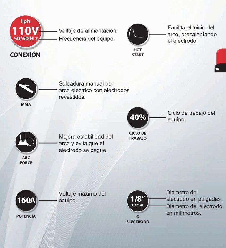
Screenshot from my phone showing some features of an inverter type welding machine.
In this type of welding machines, conventional transformers are replaced by switched-mode power supplies. They transform the low frequency alternating current that we have in our homes into direct current. Then this direct current is converted into alternating current again but at high frequencies, which allows the use of other types of more compact transformers. Once this high frequency alternating current is obtained, it must be converted to direct current once again, and it is this direct current that is used to create the electric arc for welding.
This type of welding machines tend to fail more frequently, so it is essential to know the correct way to use them in order not to exceed their capacities and thus avoid breakages due to a bad operation.
A fundamental factor to take into account for its correct use, is the duty cycle of the machine, which is nothing more than the time that the machine can work continuously within a period of 10 minutes before it needs to cool its components, this duty cycle is expressed in percent.
For example, an inverter welder with a duty cycle of 40% can operate for 4 minutes and the remaining 6 minutes must be at rest to ensure cooling. If the duty cycle is exceeded, there is a risk of overheating of the internal components of the welder and failure of the welder.
In this repair I will show you how a forced work where the work cycle of the machine was not respected resulted in damages in the copper tracks of the current output connections, which caused that it was not possible the formation of the welding arc in the electrode.
The model of this machine is F200, brand Furius. And in the following image you can appreciate its characteristics, where it is reflected that its use is ideal for ornamenters, non-intensive work or occasional work.
- Manual
electric arc welding
with
coatedelectrodes
(MMA) - Improves
arcstability
and prevents the
electrode from
sticking (ARC FORCE). - Facilitates
arc starting
by preheating
the electrode (HOT START) - Can weld up to 1/8" (3.2 mm) on
stick electrodes.
-It allows the use of 6013, 7018 and
6011 electrodes
, - Amperage range of 10-200 Amps.
- Working cycle of 40%.
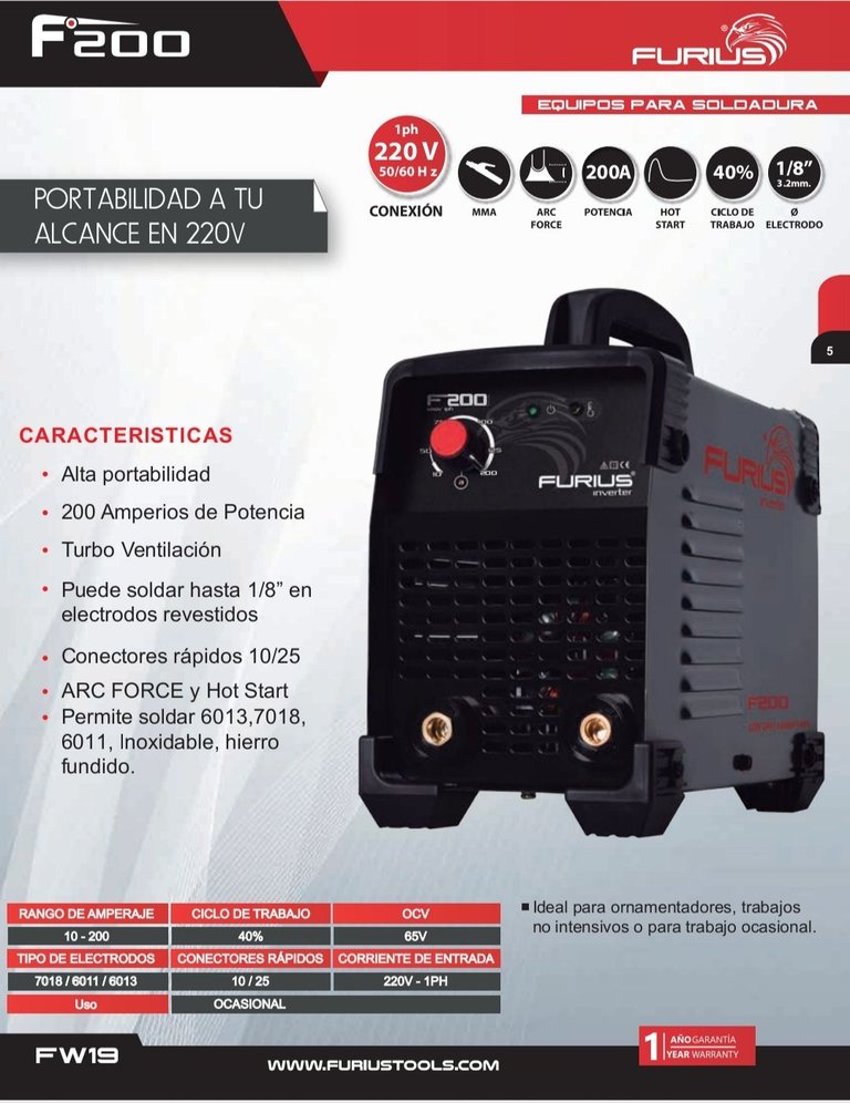
Screenshot from my phone showing the features of the Furius F200 welder.
REPARING THE FURIUS F200
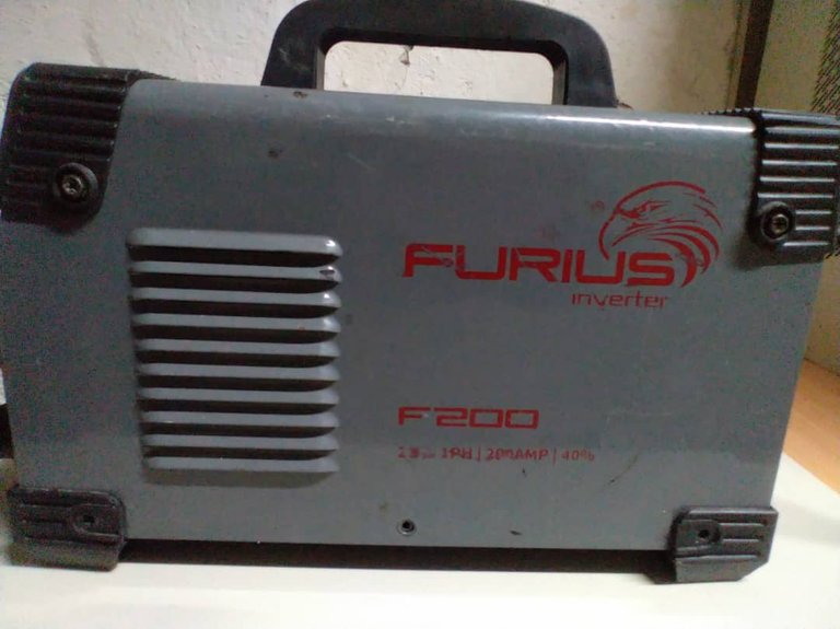
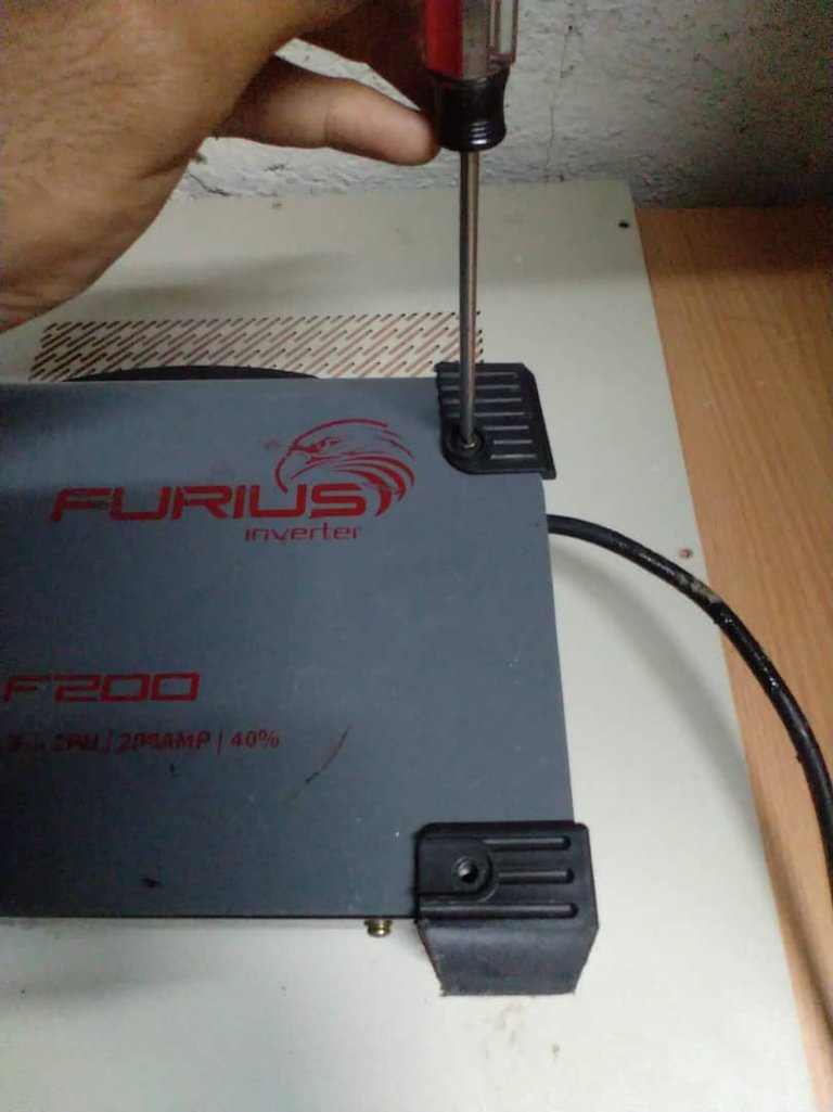
First, using a slotted screwdriver, remove the screws from the machine.
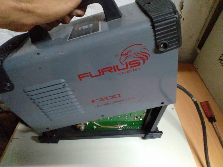
Pull the cover upwards
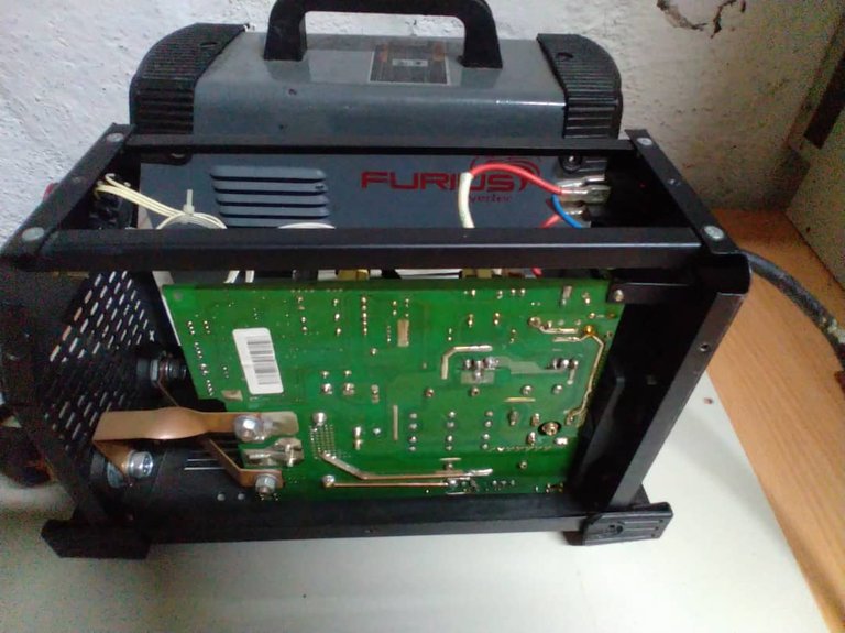
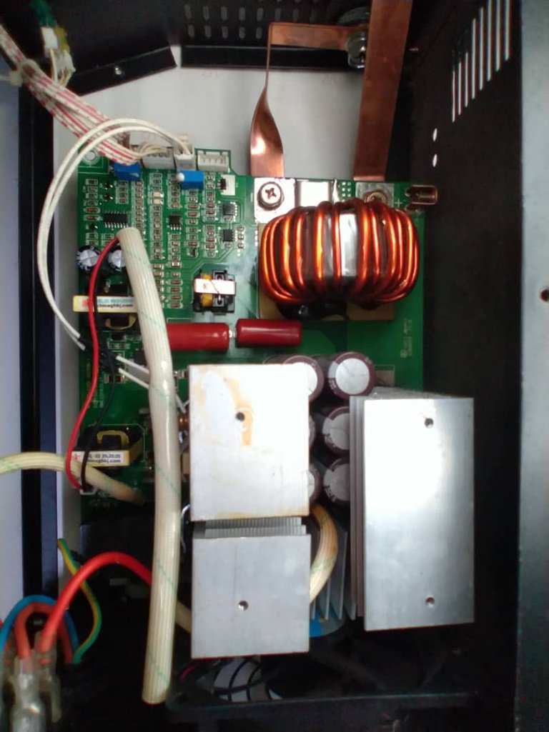
-Remove the electronic board from the machine structure, always marking the position of each card so that they can be put back in place when reassembling the machine.
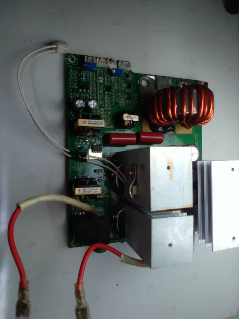
-A visual inspection of the board revealed the problem, since the copper tracks were destroyed and burned due to the intensive work that was given to the machine.
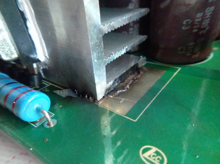
Destroyed copper track under the heatsink of the Schottky diodes that convert the high-frequency alternating current outputs to direct current.
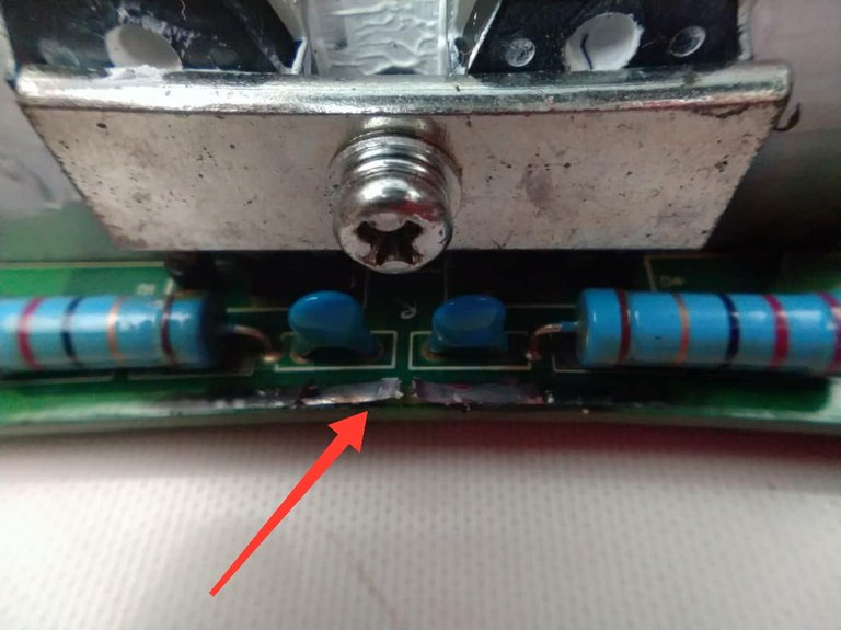
Another copper track destroyed
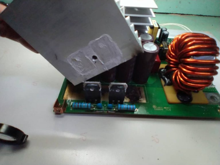
I removed the heatsink to see the total damage.
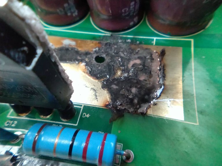
Track totally destroyed
Using the multimeter on the diode measuring scale, I check the condition of the Schottky diodes after removing them from the board.
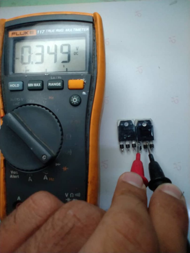
The diodes are in good condition, since the reading on the multimeter is normal for this type of diode.
REBUILDING THE TRACKS
To rebuild the tracks, it was first necessary to clean the copper surface and remove all the slag from the burns.
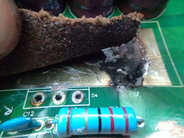
With the help of a sandpaper I managed to clean the copper surface well
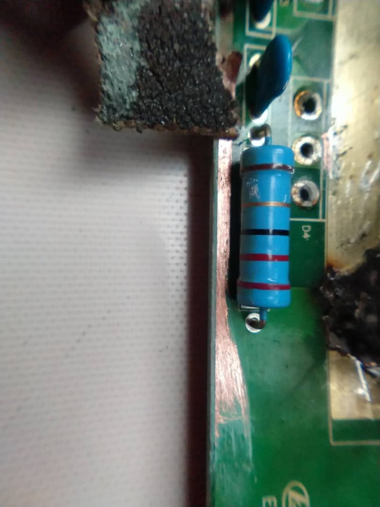
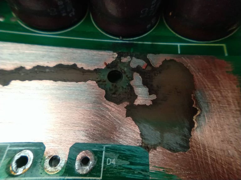
After cleaning the surface, the next step was to apply a tin bath with a soldering iron and tin wire.
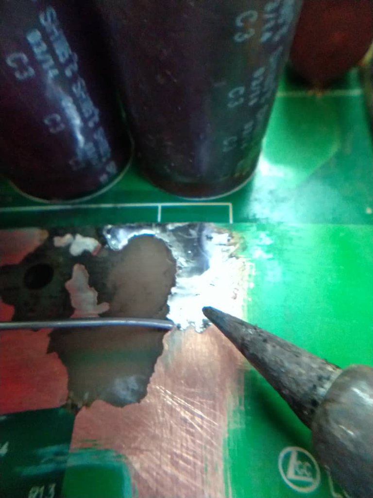
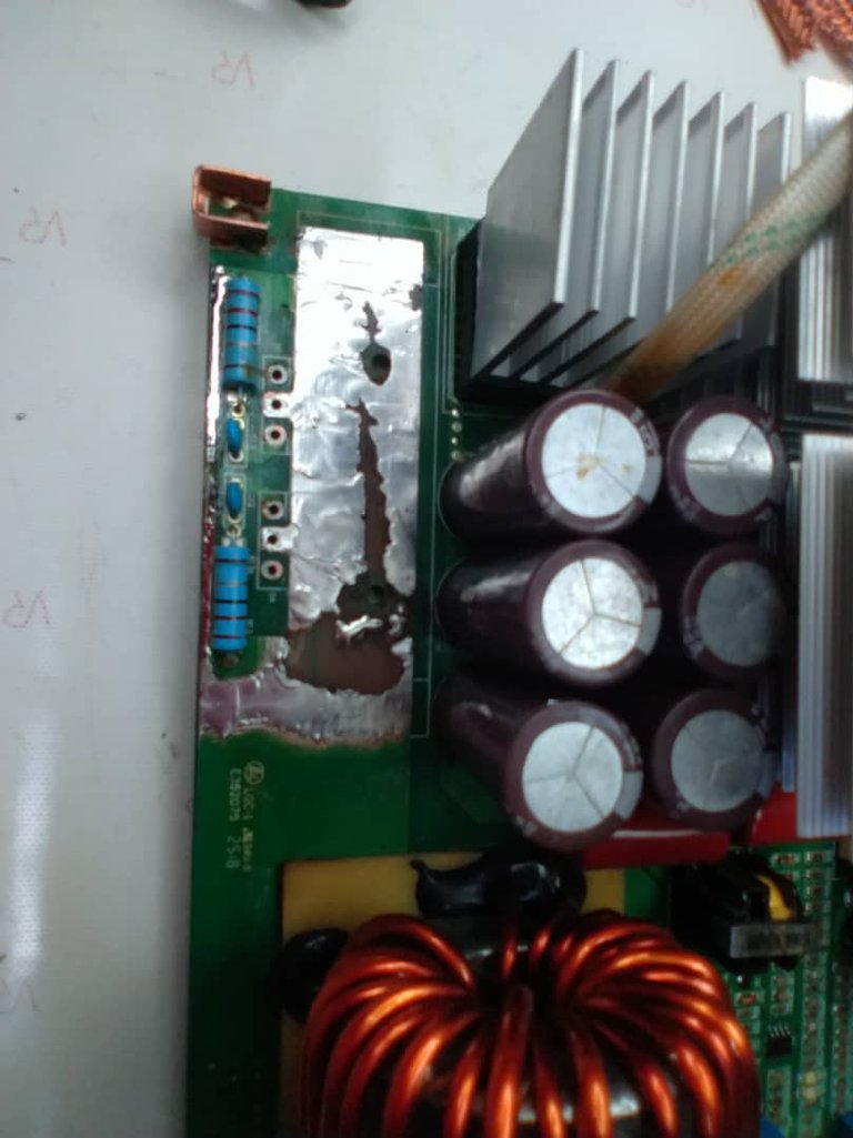
Once the entire damaged surface was tinned, the next step was to make a bridge to join the interrupted connections. To make this bridge it was necessary to recycle the wire mesh that covered a piece of coaxial cable for television signals.
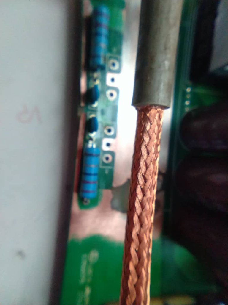
Internal mesh of a coaxial cable for TV signals
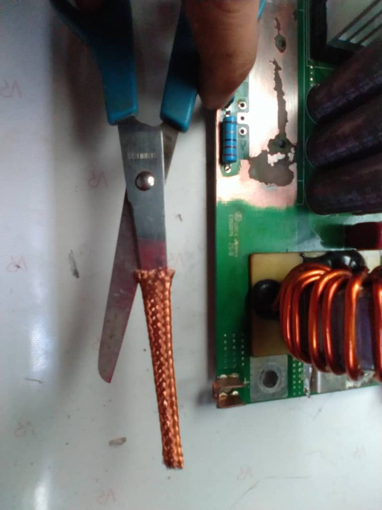
I took a piece of mesh and expanded it by applying a cut with the scissors.
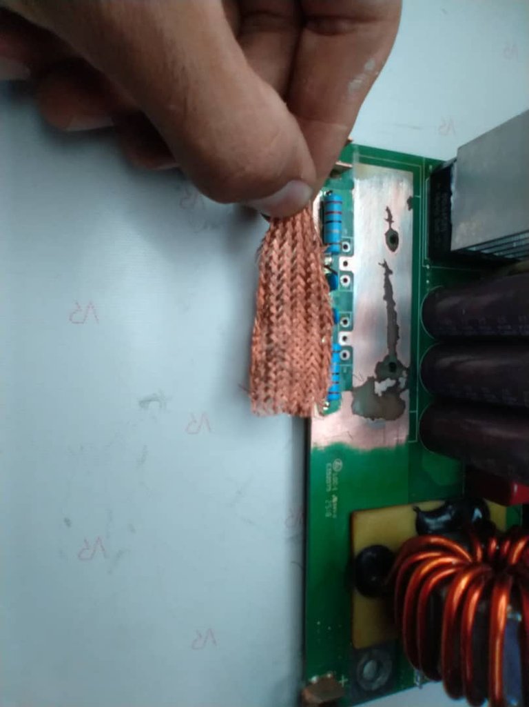
Then with the help of the soldering iron and tin, and using the section of copper mesh, I made the bridge to recover the lost connections.
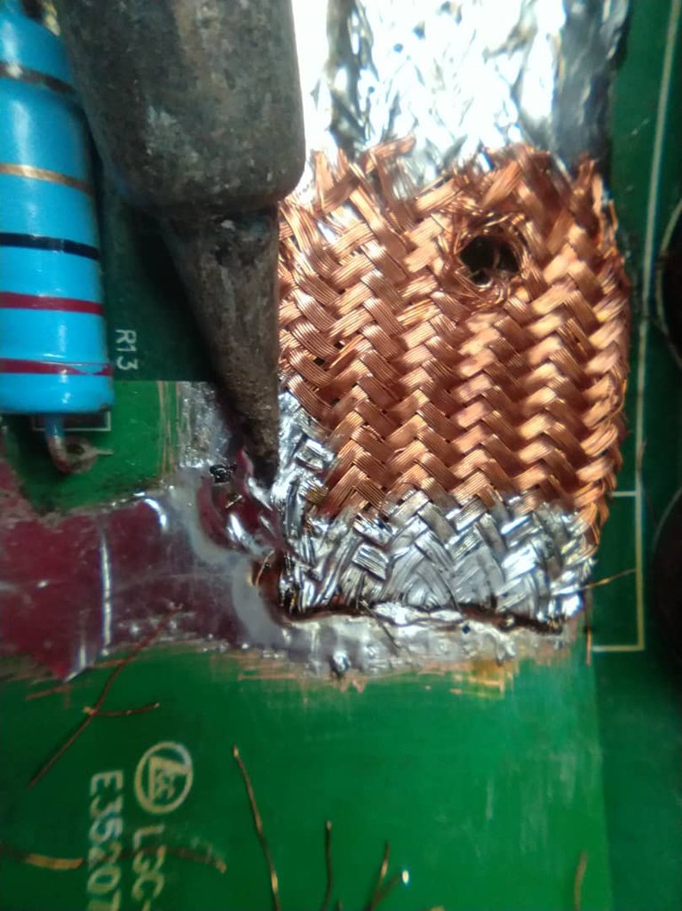
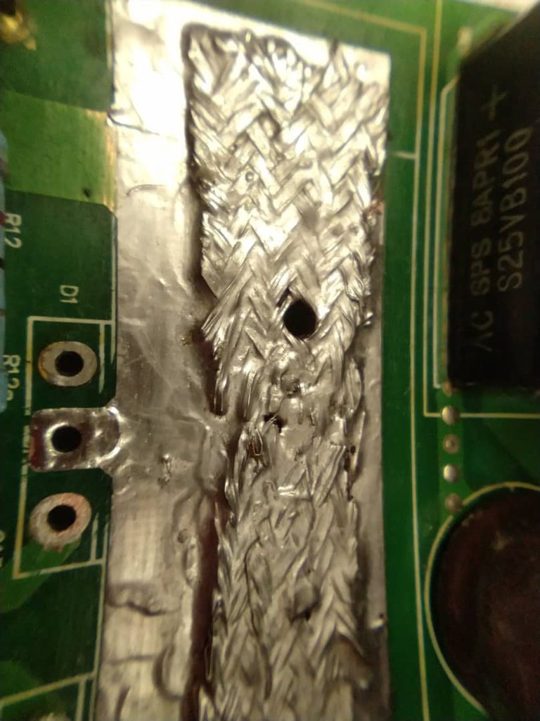
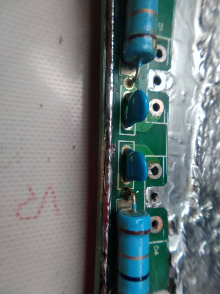
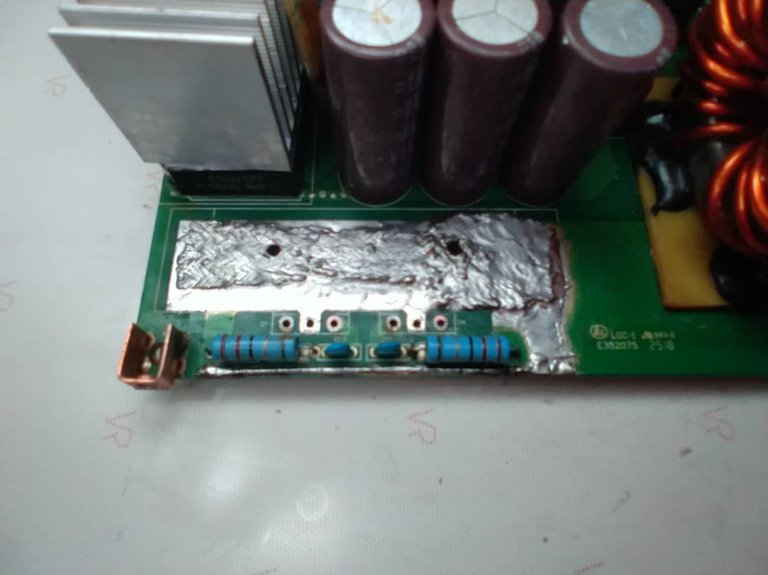
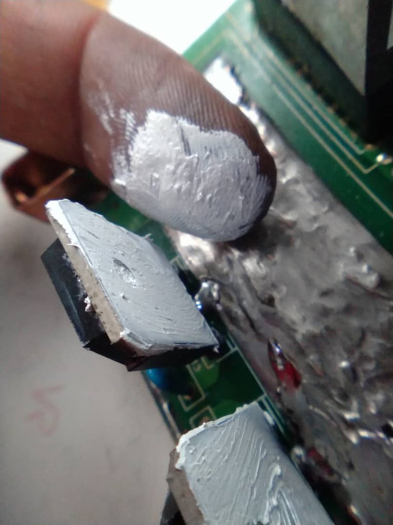
The tracks are already rebuilt, now I put the diodes back in place, and apply thermal paste to achieve an optimal heat transfer from the diodes to the heatsink, thus avoiding their destruction or malfunction.
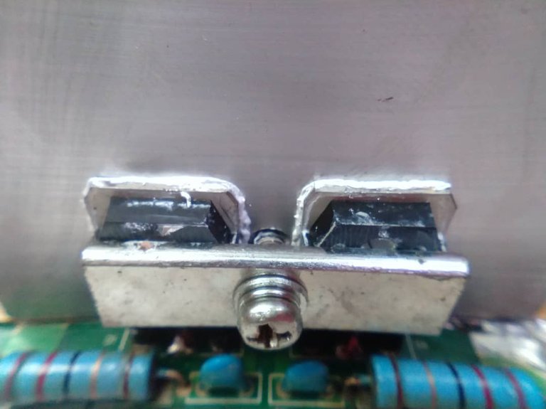
I replace the heatsink and tighten the screw.
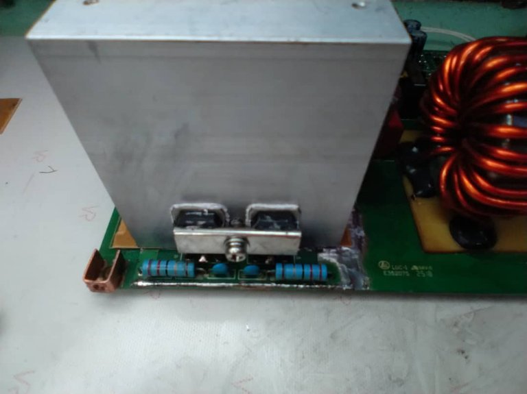
Ready, after rebuilding everything I reassemble the machine and check its operation.
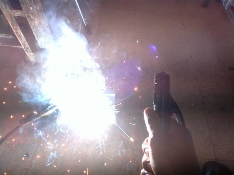
This way this inverter type welding machine is repaired. Fortunately the damage was only to the tracks and the tracks were interrupted before the semiconductor components were damaged, otherwise the cost of the damage would have been higher.
Before operating this type of welding machine, it is important to know its characteristics, and to use it respecting the parameters proposed by the manufacturer, since forcing it to work beyond its capabilities will only cause a breakdown in the equipment.
I hope this content will help you.
Have a nice day, see you next time 😉
The photos were taken with my Xiaomi Redmi Note 6 cell phone.
Screenshots, edited on my phone.
Cover image created in Canva
Text translated to English in Deepl translator.
You can see me atFacebook
ESPAÑOL
Hola mis amigos, hoy estoy por acá una vez más compartiendo con ustedes esta experiencia donde les muestro como hice la reparación de una máquina de soldar del tipo inverter.
Gracias al avance tecnológico y el empleo de los semiconductores estas máquinas del tipo inverter son una buena alternativa a las máquinas de soldar convencionales, las cuales son muchos más grandes y pesadas, debido a que emplean grandes transformadores para su funcionamiento.
El empleo de los semiconductores modernos permite fabricar máquinas mucho más compactas, y de menor peso, lo que garantiza que sean portátiles, además es posible ajustar la corriente de salida mediante un potenciómetro y garantizan un arco de soldadura más estable al trabajar con corriente directa a la salida de la máquina.

Captura de pantalla de mi teléfono donde se muestran algunas características de una máquina de soldar tipo inverter
En este tipo de soldadoras se sustituyen los transformadores convencionales por fuentes conmutadas. En ellas se transforma la corriente alterna de baja frecuencia que tenemos en nuestras casas a corriente directa. Luego se convierte esta corriente directa en corriente alterna nuevamente pero a altas frecuencias, lo que permite emplear otros tipos de transformadores más compactos. Una vez que se obtiene esta corriente alterna de alta frecuencia se debe convertir a corriente directa una vez más, y es esta corriente directa la que se emplea para crear el arco eléctrico de la soldadura.
Este tipo de máquinas de soldar suelen fallar con mayor frecuencia , por lo que es fundamental conocer la forma correcta de su empleo para no sobrepasar sus capacidades y así evitar roturas por una mala operación de la misma.
Un factor fundamental a tener en cuenta para su correcto empleo, es el ciclo de trabajo de la máquina, el cuál no es más que el tiempo que la máquina pude trabajar de forma continua dentro de un periodo de 10 minutos antes que necesite enfriar sus componentes , este ciclo de trabajo se expresa en porciento.
Por ejemplo una soldadora inverter con un ciclo de trabajo del 40% puede operar durante 4 minutos y los restantes 6 minutos deben ser de reposo para garantizar su enfriamiento. Si se sobrepasa el ciclo de trabajo se corre el riesgo de sobrecalentamiento en los componentes internos de la soldadora y una avería en la misma.
En esta reparación te mostraré como debido a un trabajo forzado dónde no se respetó el ciclo de trabajo de la máquina trajo como consecuencias daños en las pistas de cobre de las conexiones de salida de corriente, lo que provocaba que no fuera posible la formación del arco de soldadura en el electrodo.
El modelo de esta máquina es F200, marca Furius. Y en la siguiente imagen se aprecian sus características, donde se refleja que su uso es ideal para ornamentadores, trabajos no intensivos o trabajos ocasionales.
- Soldadura manual por
arco eléctrico con electrodos
revestidos .(MMA) - Mejora de la estabilidad del
arco y evita que el
electrodo se pegue (ARC FORCE). - Facilita el inicio del
arco, precalentando
el electrodo. (HOT START) - Puede soldar hasta 1/8” (3.2 mm) en
electrodos revestidos.
-Permite emplear electródos 6013, 7018 y
6011, - Rango de amperaje de 10-200 Amperios.
- Ciclo de trabajo del 40%

- Captura de pantalla de mi teléfono donde se muestran las características de la soldadora Furius F200*
REPARANDO LA FURIUS F200

Primeramente con ayuda de un destornillador de estría retiramos los tornillos de la máquina.


Tirar de la tapa hacia arriba


-Extraer la placa electrónica de la estructura de la máquina, marcando siempre la posición de cada ficha para poder colocarlas nuevamente en su lugar en el momento de armar la máquina.

-Al realizar una inspección visual de la placa pude percatarme del problema, ya que se observaban pistas de cobre destruidas y quemadas producto al trabajo intensivo que se le dió a la máquina.

Pista de cobre destruida debajo del disipador de los diodos Schottky que convierten las salidas de corriente alterna de alta frecuencia a corriente directa.

Otra pista de cobre destruida

Retiré el disipador para ver el daño total

Pista totalmente destruida
Con ayuda del multímetro en la escala de medición de diodos, compruebo el estado de los diodos Schottky después de haberlos retirado de la placa.

Los diodos se encuentran en buen estado, ya que en este tipo de diodos es normal la lectura que se observa en el multímetro
RECONSTRUYENDO LAS PISTAS
Para reconstruir las pistas, primeramente fue necesario limpiar la superficie de cobre y eliminar toda la escoria producto de las quemaduras.

Con ayuda de una lija logré limpiar bien la superficie de cobre


Después de tener bien limpia la superficie lo siguiente fue aplicar un baño de estaño con ayuda del soldador cautín y alambre de estaño.


Una vez que toda la superficie dañada se encuentra estañada, lo siguiente fue realizar un puente para unir las conexiones interrumpidas. Para realizar este puente fue necesario reciclar la malla de alambre que recubría un trozo de cable coaxial para señales de televisión.

Malla interna de un cable coaxial para señales de TV

Tomé un trozo de malla y lo expandi aplicando un corte con las tijeras.

Luego con ayuda del cautín y el estaño, y utilizando la sección de malla de cobre, realicé el puente para recuperar las conexiones perdidas.


Ya las pistas están reconstruidas, ahora vuelvo a colocar los diodos en su lugar, y le aplico pasta térmica para lograr una óptima transferencia de calor desde los diodos hacia el disipador, evitando con esto su destrucción o un mal funcionamiento.


Coloco nuevamente el disipador y ajusto el tornillo

Listo!, después de reconstruir todo armo nuevamente la máquina y compruebo su funcionamiento.

De esta forma queda reparada esta máquina de soldar del tipo inverter. Por suerte los daños fueron solo en las pistas y estas se interrumpieron antes de que sufrieran daños los componentes semiconductores, pues de haber sido así el costo del daño sería mayor.
Antes de operar este tipo de máquinas de soldar es importante conocer sus características, y utilizarla respetando los parámetros que propone el fabricante, ya que forzarlas a trabajar por encima de sus capacidades solo provocará una avería en el equipo .
Espero que este contenido te sirva de ayuda.
Tengan un buen día, hasta la próxima 😉
Las fotos fueron tomadas con mi celular Xiaomi Redmi Note 6.
Capturas de pantalla, editadas en mi teléfono.
Imagen de portada creada en la a Canva
Puedes verme en Facebook
Waoo mano espectacular manual de procedimientos al detalle, muchas gracias por compartir este tipo de contenido. Saludos ✨
Es un placer hermano, gracias por pasar y comentar, que bueno que te sirve de algo el contenido. Saludos
Amigo que magistral reconstruction, lamento no haber visto tu publicación antes, quedo excelente, verte trabajar de esta manera me hace recordar mis primeros dias con la electrónica, ya han pasado tantos años que pocas cosas recuerdo jeje.
Gracias por tus palabras hermano, es un placer compartir este contenido en la comunidad, me alegro que te haya recordado una etapa de tu vida. Saludos
Wow hermano que gran trabajo has hecho aquí, sin duda un trabajo excepcional.
Hola hermano, gracias por las palabras, fue un trabajo que disfrute mientras lo hacía jjjj, por suerte tubo reparación. Gracias por comentar, saludos
Aquí hiciste un excelente trabajo amigo, la reconstrucción de la pista fue muy ingeniosa, utilizaste malla para desoldar, un buen material porque es de cobre.
Si, lo importante es utilizar materiales reciclados siempre que se pueda y que garantice un resultado óptimo, Gracias por comentar, saludos hermano.
Congratulations @darknapol! You have completed the following achievement on the Hive blockchain And have been rewarded with New badge(s)
Your next target is to reach 800 comments.
You can view your badges on your board and compare yourself to others in the Ranking
If you no longer want to receive notifications, reply to this comment with the word
STOPCheck out our last posts: